690V/800V Anti-Pollution Static Var Generator SVG — High-Voltage Power Quality Series

Tags 690V/800V Anti-Pollution SVG, high-voltage static var generator, dust-proof static var generator, harsh-environment SVG, anti-corrosion power factor correction, heavy-duty SVG

Function: Reactive Power Compensation, Power Factor Correction, Imbalance Phase Balancing

Rated Voltage: 690/800 VAC

Power Capacity: 50/75/100/150/200A single module (unlimited for parallel)

Efficiency: ≥ 97%

Compensation Performance: up to 97%

Nominal Frequency: 50/60HZ

Connection Type: 3 Phase 3 Wire / 3 Phase 4 Wire

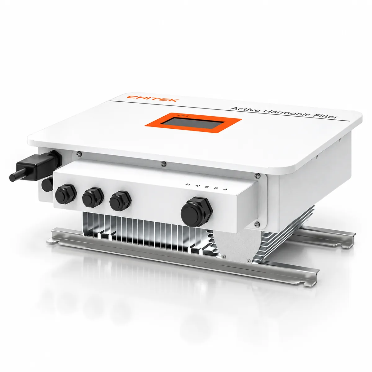
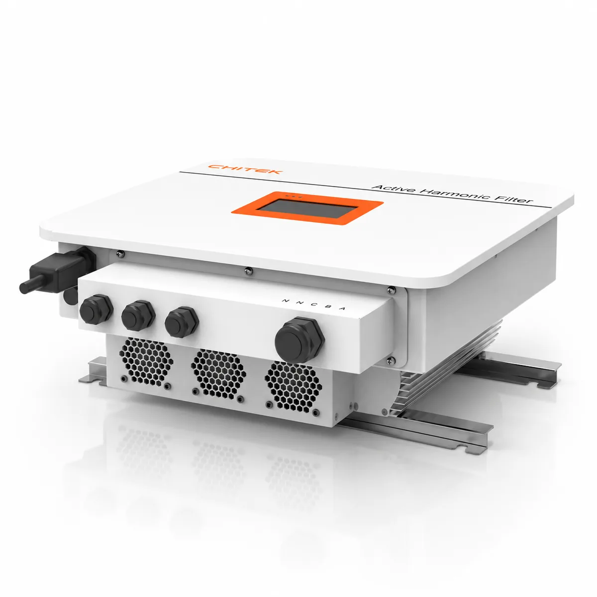
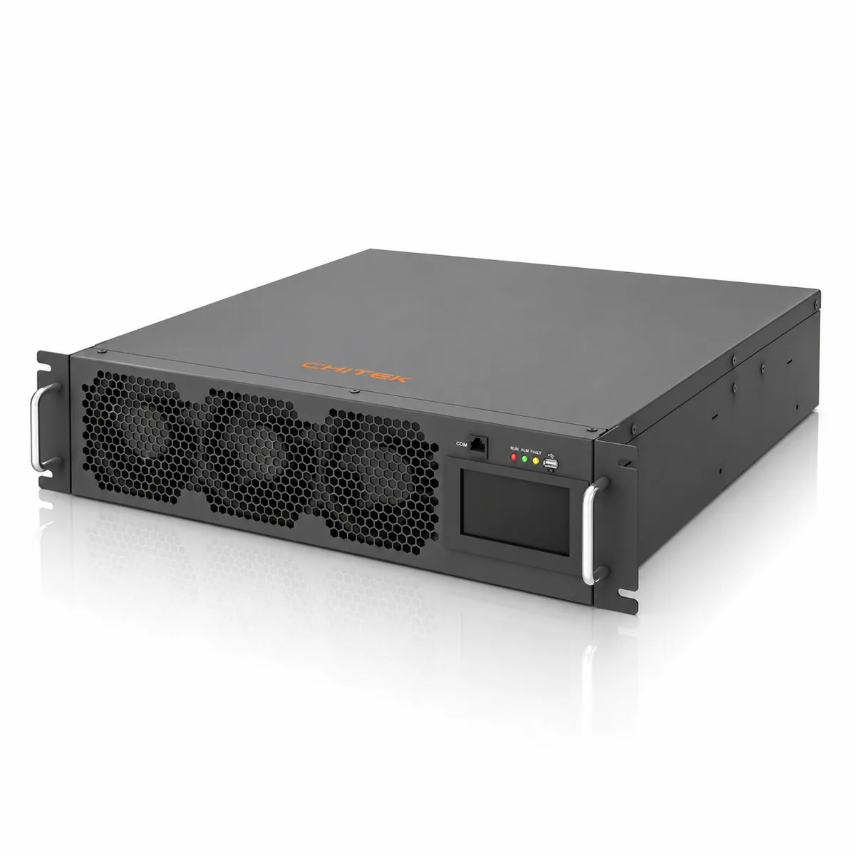
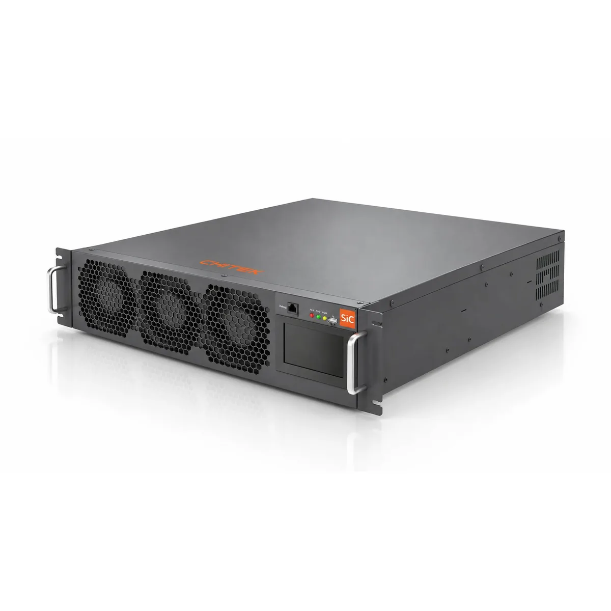
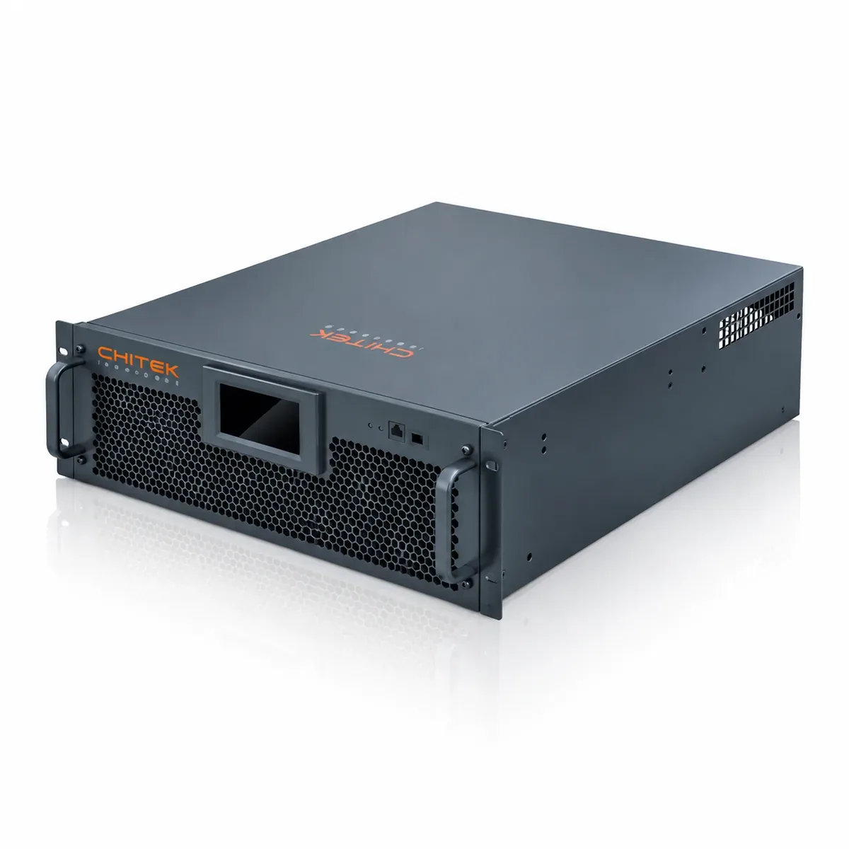
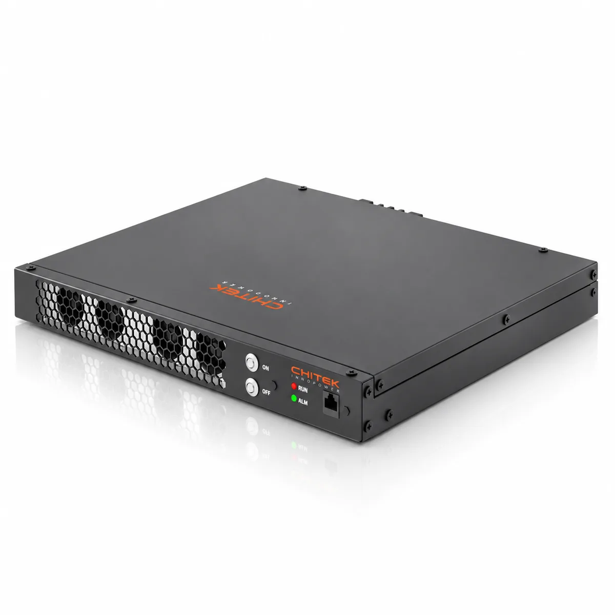
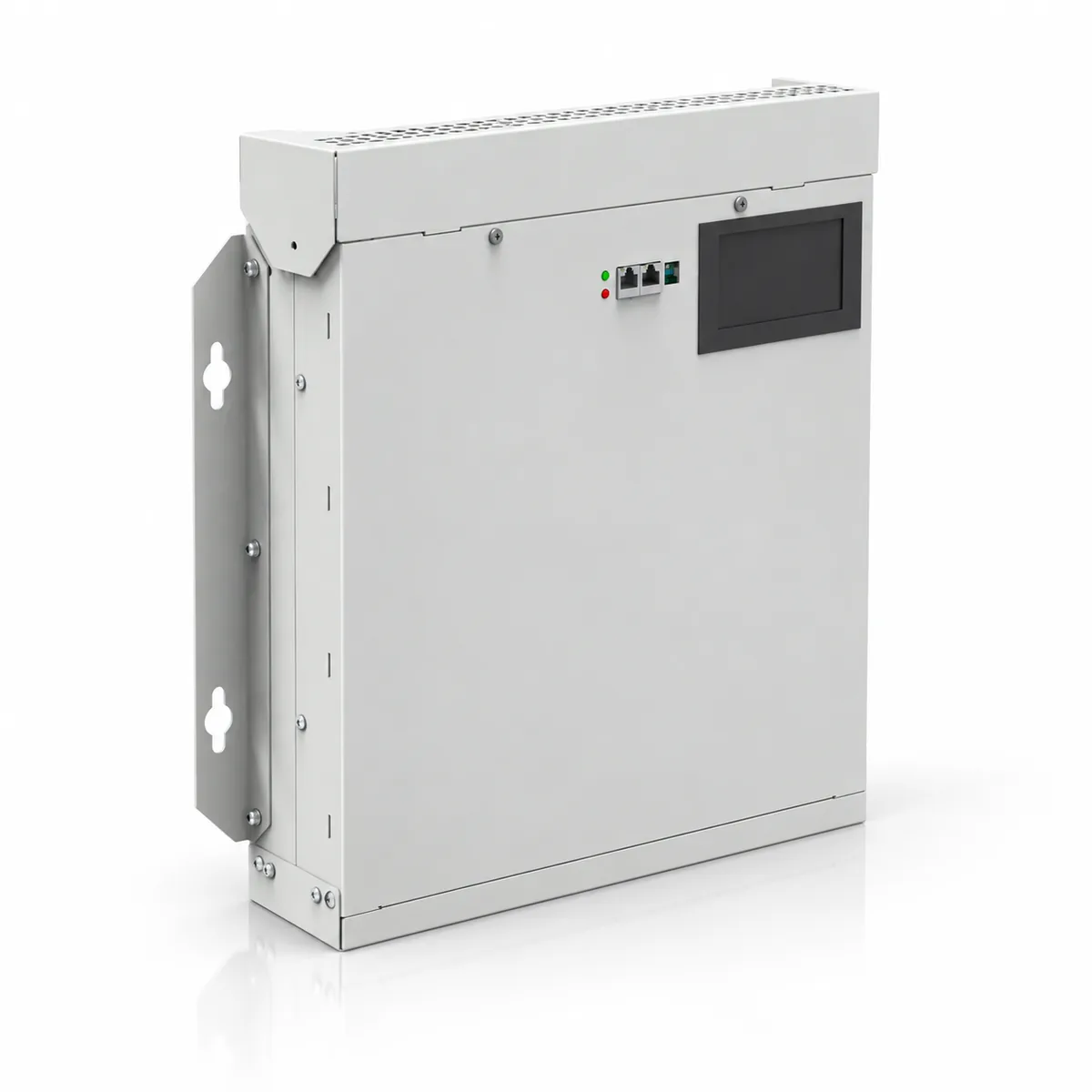
Installation: Wall mounted/Rack mounted/Cabinet

Warranty: Standard 2 years/negotiable

Configure your SKU

SKU: —

Pick voltage, protection rate, capacity, wiring and installation — the selector fills in the matching part number.

Rated Voltage

Protection Rate

Power Capacity

Wiring

Installation

CHITEK 690V/800V Anti-Pollution Static Var Generator SVG

Product

690V/800V Anti-Pollution Static Var Generator SVG

Voltage level

208/400/480/690/800 VAC

Product Description

A power factor that stays on target on a CHITEK Static Var Generator translates directly into a more dependable electrical network and lower running costs. By supplying the reactive current locally instead of drawing it from the utility, the generator relieves the extra loading that makes cables, transformers and switchgear run hot, and it removes the reactive penalty charges that plant teams otherwise pay month after month.

Because the reactive demand is met at the point of use, motors, transformers, switchgear and cables carry less current for the same useful work, so their service life is extended and maintenance schedules become lighter. On new-build projects, engineers can also revisit the practice of oversizing distribution equipment purely as a defence against poor power factor — a smaller, better-utilised design is usually enough.

Graphical HMI

Direct control, configuration, monitoring and power-quality analysis from the front panel — no PC required.

Comprehensive Measurements

RMS voltages and currents, power factor before/after, system frequency, load factor and the compensation current the unit is delivering right now.

Power Factor Correction

Dynamic correction for both lagging and leading power factor without capacitor-step switching.

Load Balancing

Balances three-phase systems and relieves neutral current in 3P4W networks.

Low Thermal Loss

the IGBT bridge keeps losses low and efficiency at 97% or better, cutting cooling demand.

Flexible & Modular

Modular design embedded in standard or customized cabinets, with parallel expansion and factory ODM support.

Technical Parameters

Module Parameters
Rated Voltage800VAC690VAC
Rated CurrentAPF 85AAPF 100A
Power CapacitySVG 120KvarSVG 120Kvar
System Parameters
Rated Input Voltage800/690VAC (-20%~+10%)
Grid Frequency50Hz (range: 47Hz~53Hz), 60Hz (range: 57Hz~63Hz)
Number of Parallel Connections≤ 16 units
EfficiencyUp to 98%
Grid StructureThree-phase three-wire
Current Transformer150/5~30,000/5
Performance Indicators
Harmonic Compensation Range2~50 times
Harmonic Attenuation>95% (rated load)
Quick Response Time< 50µs
Full Response Time< 5ms
Target Power Factor-1~+1, capacitive and inductive continuously adjustable
Compensation ModeHarmonic suppression / reactive power compensation / unbalance compensation, any combination of 11 modes
Noise Indicator<60dB
Communications & Monitoring
Communication InterfaceRS485, WiFi, 4G, CAN
Communication ProtocolModbus protocol (RTU or TCP/IP)
Module Display Interface4.3 inch touch screen, LED indicators, independent touch screen
Mechanical Properties
Mounting OptionsWall-mounted / Rail-mounted
Dimensions W×D×H (mm)480×600×175
Net Weight40kg
ColorIndustrial black (RAL7021), customizable upon request
CT Connection ModeSupport the source side / load side
Environmental Requirements
Altitude≤1500m; between 1500m and 4000m, according to GB/T3859.2, power decreases by 1% for every 100m increase
Operating Temperature-40℃~+65℃
Relative Humidity5%~95%, no condensation
Protection LevelIP20, other IP levels customizable
Related Qualifications and Standards
Standards ComplianceIEC61000-3-6, IEC61000-6-4, ER G5/4, EN 62477-1
CertificationCE, CQC

WHY CHITEK 690V/800V Anti-Pollution Static Var Generator SVG?

Easy to install and commission

Hardware

  • CT Wiring: Isolated S1/S2 terminals; error-proof CT terminal blocks (pre-fabricated cables included as standard). Flange-locking design prevents open circuits.
  • RJ45 ports for module paralleling and module-to-control panel connections. Ports integrate power, RS-485, and CAN communication. Pre-fabricated cables come as standard for plug-and-play, significantly reducing wiring time.

Software

Easy software operation, and simple hardware installation. Only power cables and a set of CT to set up 690V/800V Anti-Pollution Static Var Generator SVG. The Automatic fine-tuning function realizes intelligent and excellent compensation effects, bringing users a simple and efficient commissioning experience.

Potting Protection

Protects electronic circuits against contamination without compromising heat dissipation

Smart Sleep Mode

  • Load-based start/stop prevents prolonged operation under low-load conditions
  • Duty cycling for low-load modules
  • Enhanced energy efficiency and extended lifespan

Resonance suppression

  • Proprietary algorithm that detects line conditions and automatically adjusts parameters.
  • Compatible with a wide range of complex load types

Manufacturing & Quality Assurance Capabilities

The 690V/800V Anti-Pollution Static Var Generator SVG is built in our own 2,300 m² plant under an ISO 9001:2015 quality system — from incoming inspection to burn-in testing, every stage is completed and signed off under our own roof.

ISO 9001:2015 quality system

SGS-certified quality management governs design, procurement, production and final release — published parameters match actual shipped performance.

Complete in-house production line

Component procurement, SMT/DIP assembly, board FCT, IPQC, safety-compliance testing, ATE fixture test, potting and aging — all completed inside our own facility.

Every unit burn-in tested

A self-developed aging cabinet with module fixture testing (patent CN22268956U) runs each unit through full burn-in, followed by a post-aging final quality check.

Proven in the field

CHITEK filters are in service in more than 10 countries, with multilingual interfaces and factory technical support for overseas commissioning.

Certifications

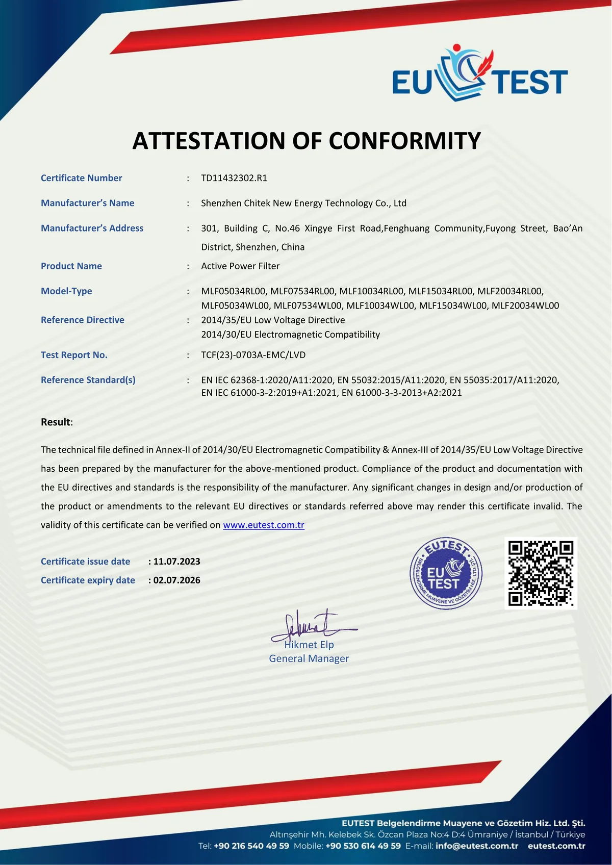
EUTEST Attestation of Conformity TD11432302.R1 for the CHITEK Active Power Filter, covering EU Low Voltage Directive 2014/35/EU and EMC Directive 2014/30/EU

CE — LVD & EMC (EUTEST, 2023)

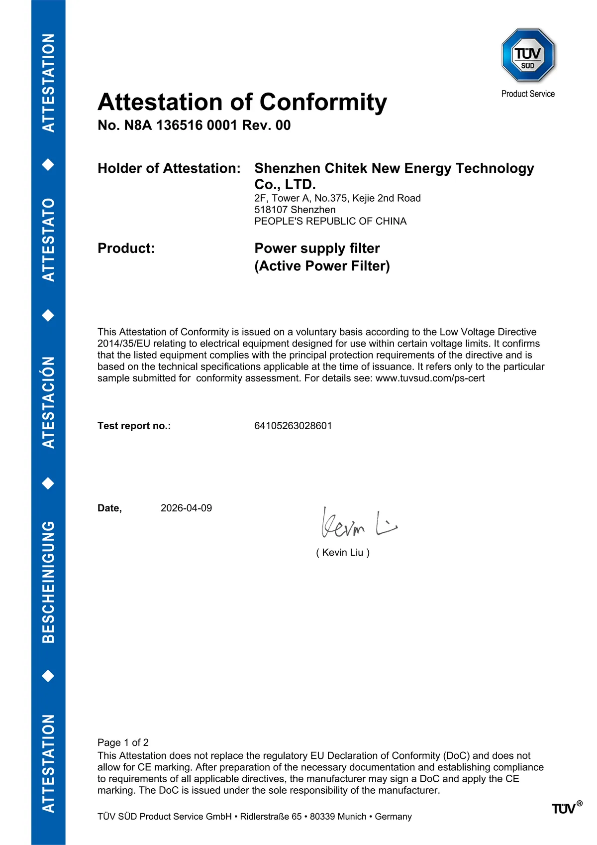
TÜV SÜD Attestation of Conformity No. N8A 136516 0001 Rev. 00 for the CHITEK Active Power Filter, issued under EU Low Voltage Directive 2014/35/EU

LVD 2014/35/EU (TÜV SÜD, 2026)

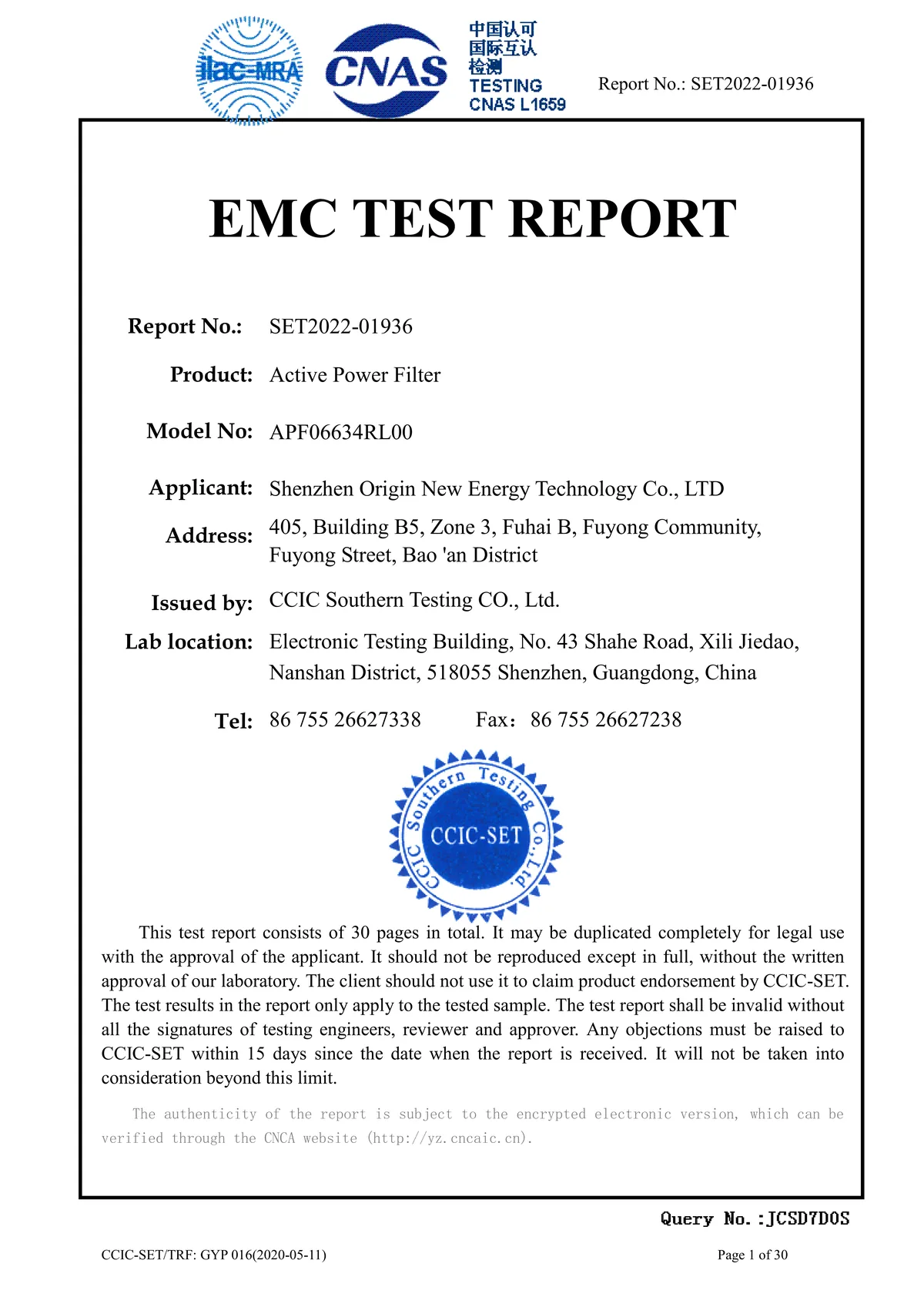
EMC test report No. SET2022-01936 for the Active Power Filter, issued by CCIC Southern Testing Co., Ltd. (CNAS L1659 accredited laboratory)

EMC test report (CCIC-SET, 2022)

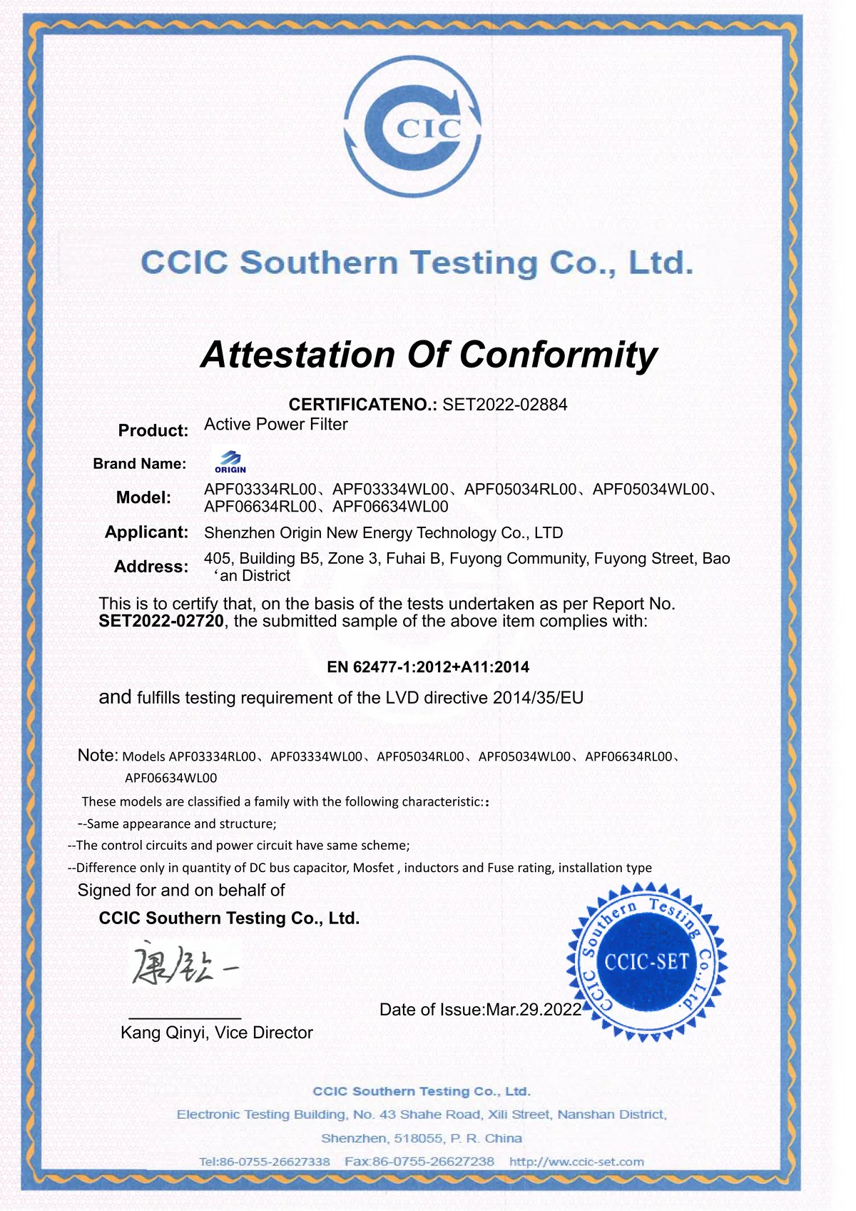
CE Attestation of Conformity No. SET2022-02884 for the Active Power Filter, issued by CCIC Southern Testing Co., Ltd. to EN 62477-1:2012+A11:2014 and EU Low Voltage Directive 2014/35/EU

CE / LVD 2014/35/EU (CCIC-SET, 2022)

Want a network that runs cooler, trips less often and stays inside specification? Send us your load details and our engineers will propose a configuration and quote it against your actual requirements — not a catalogue guess.

Request a Consultation

FAQs About the 690V/800V Anti-Pollution Static Var Generator SVG

Q1: What is an static var generator (SVG)?

A static var generator is a power-electronics device that measures the load current with an external CT, separates the reactive component from the active current with a DSP, and injects or absorbs the compensation current through a fast inverter bridge. The utility then sees only the fundamental, with the power factor at the level you set.

Q2: How does the SVG work?

An external CT samples the load current; a DSP/FPGA separates the reactive component and the phase imbalance in real time; the inverter bridge then injects or absorbs the compensation current continuously rather than in switched steps. The result is a stepless correction that holds power factor at target at the point of common coupling.

Q3: What capacity and voltage range is available?

50 A – 200 A per module (parallel expandable, unlimited), 3P3W/3P4W, covering 208–690V. Modules parallel without a practical limit to reach 3000 A and beyond for large plants.

Q4: Can it hold power factor and balance loads at the same time?

Yes. A selectable priority function covers reactive power compensation, power factor correction and three-phase balancing. In 3P4W mode it also cancels the accumulated neutral current.

Q5: How is it installed and what protection rating does it have?

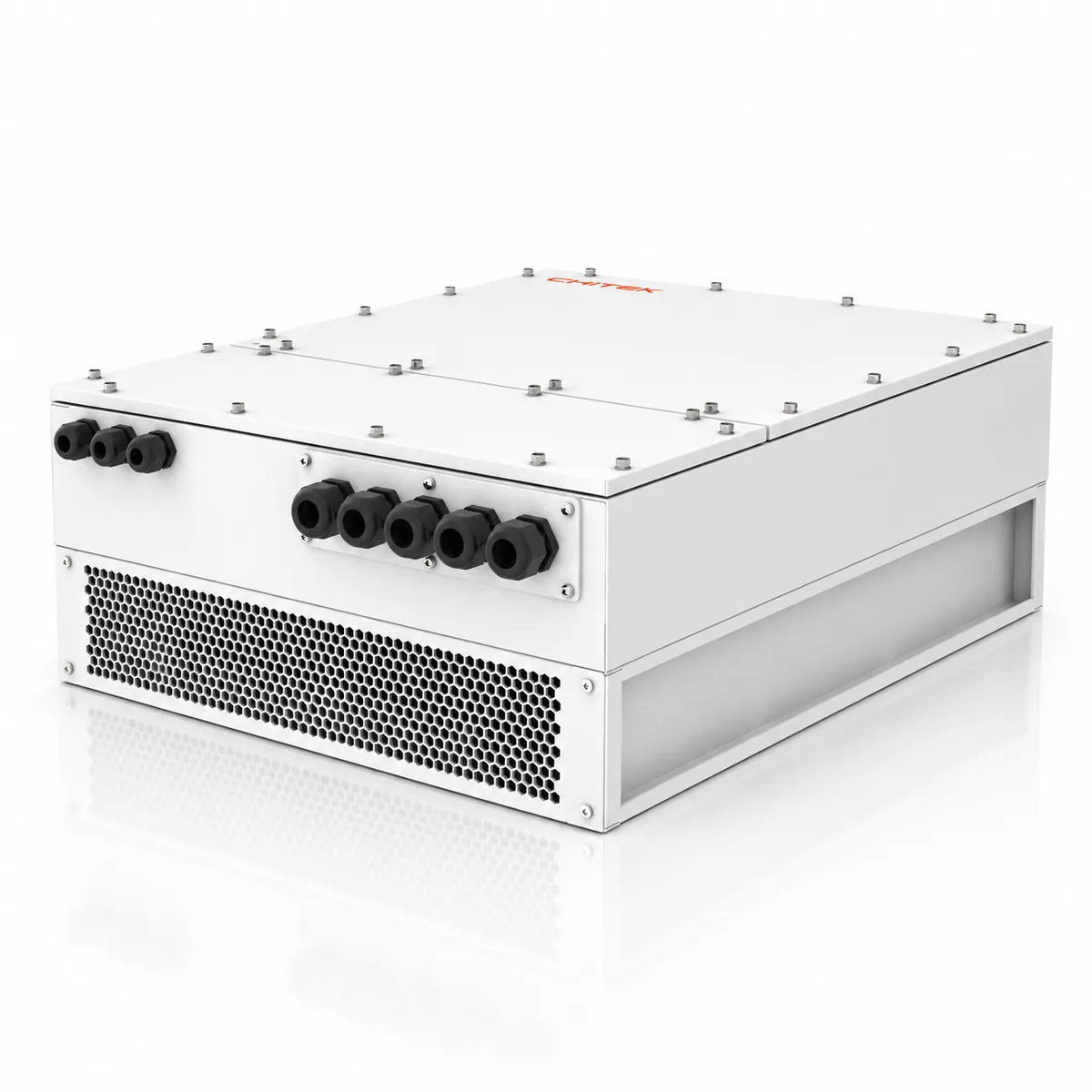
Installed as wall-mounted or rack / cabinet type; rated IP20, IP30 (customizable). The enclosure is built for the duty cycle of industrial switchrooms and can be customized for harsher or outdoor sites.

Q6: How do I confirm the right model for my site?

Send us the load profile, voltage class and your target power factor. CHITEK supplies a selection matrix by voltage class, series and capacity, plus a sizing calculation on request.

Product Advantage: Static Var Generators vs Capacitor Banks or Reactor Banks

Aspect Capacitor Banks or Reactor Banks Static Var Generators
Response time
  • Contact-based solutions take at least 30 s to 40 s to mitigate the problem and thyristor-based solutions 20 ms to 30 ms
  • Real-time mitigation of power quality problems as the overall response time is less than 100 μs
Output
  • Depends on step sizes; cannot match load demand in real time
  • Depends on grid voltage as capacitor units and reactors are used
  • Instantaneous, continuous, stepless and seamless
  • Grid voltage fluctuation has no influence on the output
Power factor correction
  • Capacitor banks needed for inductive loads and reactor banks for capacitive loads; problems in systems with mixed loads
  • Not possible to guarantee unity power factor as they have steps; the system will be having continuous over- and under-compensation
  • Corrects simultaneously from −1 to +1 power factor of lagging (inductive) and leading (capacitive) loads
  • Guaranteed unity power factor at all times without any over- or under-compensation (stepless output)
Design & sizing
  • Reactive power studies needed to size the proper solution
  • Usually oversized to better adjust to changing load demands
  • Need to be designed taking into account system harmonics
  • Custom-built for specific load and network conditions
  • No extensive studies required as it is adjustable
  • Mitigation capacity can be exactly what load demands
  • Unaffected by harmonic distortion in the system
  • Can adapt to load and network conditions and changes
Resonance
  • Parallel or series resonance can amplify currents in the system
  • No risk of harmonic resonance with the network
Overloading
  • Possible due to slow response and/or variation of loads
  • Not possible as current is limited to the max. RMS current
Footprint & installation
  • Medium to large footprint, especially if several harmonic orders
  • Not simple installation, especially if loads upgraded frequently
  • Small footprint and simple installation as modules are compact in size; existing switchgear can be used
Expansion
  • Limited and depends on load conditions and network topology
  • Simple (and not dependent) by adding modules
Maintenance & lifetime
  • Uses components that need extensive maintenance like fuses, circuit breakers, contactors, reactors and capacitor units
  • Switching, transients and resonance reduce lifetime
  • Simple maintenance and service life up to 15 years as there is no electro-mechanical switching and no risk of transients or resonance

Application of the 690V/800V Anti-Pollution Static Var Generator SVG

Data Center

40 MW Hyperscale Data Center — Reactive Support & UPS Input Power Quality

Three 2.4 MW UPS modules running in parallel at a 40 MW hyperscale facility were circulating rectifier harmonics between units — unbalancing load sharing, thermally stressing the battery strings and triggering false PDU alarms. Three SVG-150kvar units went in on the LV bus, with AHF-200A units at the UPS input. Distortion at the UPS input fell from 14.0% to 2.8%, circulating current dropped by 80%, and the site recovered 2.6M CNY in annual energy cost.

THD 14.0% → 2.8% · circulating current down 80% · 2.6M CNY saved per year

China Static Var Generator SVG, Active Harmonic Filter Suppliers, Manufacturers, Factory - CHITEK
Industrial Manufacturing

12-inch Wafer Fab — Sub-Cycle Sag Protection

An immersion-lithography fab needs voltage sags held below 5 ms, yet utility faults 30 km away kept stripping scanner stage position — about three incidents a month, each scrapping roughly 25 wafers. Four dual-feed AHF+SVG units at the UPS front end and two SPC-100A units balancing the test floor brought sag duration back inside spec. Scanner halts stopped completely, wafer yield gained three percentage points, and payback landed under eight months.

Sag under 5 ms · zero scanner halts · wafer yield +3 points

China Static Var Generator SVG, Active Harmonic Filter Suppliers, Manufacturers, Factory - CHITEK
Commercial & Medical

2,000-Bed Hospital — Imaging & OR Power Quality

A 2,000-bed tertiary hospital with four 1,600 kVA transformers watched main-busbar THD climb past 18% after its imaging centre was expanded — enough to produce CT and MRI image artifacts and one power-quality incident in an operating theatre. Two AHF-200A units now cover the OR and imaging feeders, with one SVG-100A on HVAC reactive duty. THD settled at 4.1% under IEEE 519, transformer temperature fell 15°C and maintenance cost dropped 45%.

THD 18.3% → 4.1% · transformer down 15°C · maintenance cost −45%

China Static Var Generator SVG, Active Harmonic Filter Suppliers, Manufacturers, Factory - CHITEK